This is Potentiometer
Components:
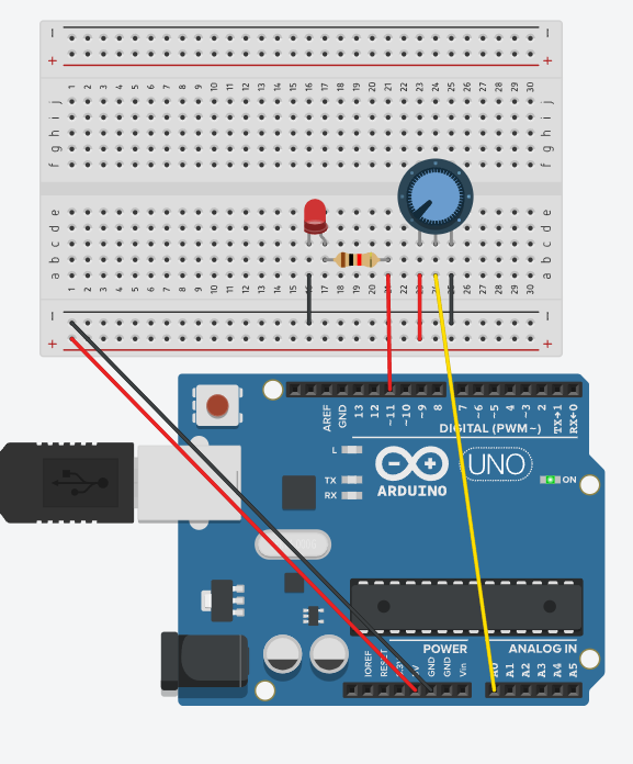
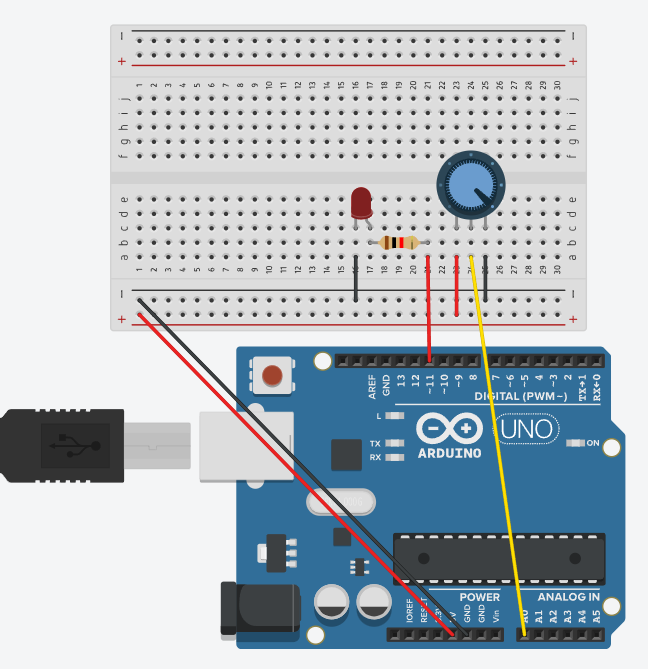
A potentiometer is used to control the speed of LED blinking.
Connecting Components
Power Connection
The red wire (5V from Arduino) goes to the positive wire on the breadboard.
The black wire (GND from Arduino) goes to the negative wire on the breadboard.
Connecting the Potentiometer
The potentiometer has 3 outputs:
The left output is connected to GND (black wire).
The right output is connected to 5V (red wire).
The middle output (output) is connected to A0 (Arduino analog input, yellow wire).
Connecting the LED
The anode (longer leg) goes to digital pin 9 on the Arduino via a resistor.
The cathode (short leg) goes to GND.
Connecting the Resistor
One output is connected to the anode of the LED.
The other output is connected to pin 9 on the Arduino.
Code
// C++ code
// int potekas = 0;
int punane = 11;
int potval = 0;
void setup(){
pinMode(punane,OUTPUT);
Serial.begin(9600);
}
void loop(){
potval = map(analogRead(potekas),0,1023,0,255); analogWrite(punane,potval);
Serial.println(potval) ; }
How it works
When you turn the potentiometer, the voltage at its center output changes.
The Arduino reads the value from A0 and converts it to a range of 0–255 (LED brightness).
The higher the potentiometer value, the brighter the LED will be.
The values are visible in the porta monitor (Serial Monitor in the Arduino IDE).
Summary
This circuit allows you to adjust the brightness of an LED using a potentiometer. It will help you understand how the Arduino’s analog input and PWM (pulse-width modulation) work to control brightness.